High Pressure Combustion Lab

Dr. Richard Yetter, Director
104 Research Building East
University Park, PA 16802
Phone: (814) 863-6375
Email: ray8@psu.edu
Dr. Eric Boyer, Assistant Director
High Pressure Combustion Lab
University Park, PA 16802
Phone: (814) 863-2264
Email: jeb19@psu.edu

Diagnostics - Real-time X-ray Radiography
As currently implemented at the HPCL, the X-ray RTR system consists of an X-ray source and X-ray image intensifier paired to a digital camera and frame capture system. The X-ray source has both large (5.5 mm) and small (3.0 mm) focal spots with continuous power ratings of 4200W and 1500W respectively, and operates with a maximum voltage up to 320 kV. The image intensifier is dual-field, having a maximum input diameter of 6" and can zoom to a 4" diameter. At the zoom setting, the limiting resolution is very high (95 line-pairs/cm), which can result in demonstrated real-world resolution of ~0.003" (~75 µm) for a geometric magnification of ~1.1x. Output of the image intensifier is captured by a 1,280 x 1,024 pixel 8-bit monochrome CMOS camera at a full-frame rate of ~30 fps. With a decreased region-of-interest (ROI), framing rate can be increased proportionally; 1100 fps for a 100 x 200 pixel ROI has been utilized for experiments measuring dynamic burning rates of solid propellant. To achieve imaging rates over 5,000 fps at full-frame resolution, or very high speeds (~10,000 fps) at reduced ROI, the current digital camera has been swapped with a Vision Research Phantom v7.3 camera.
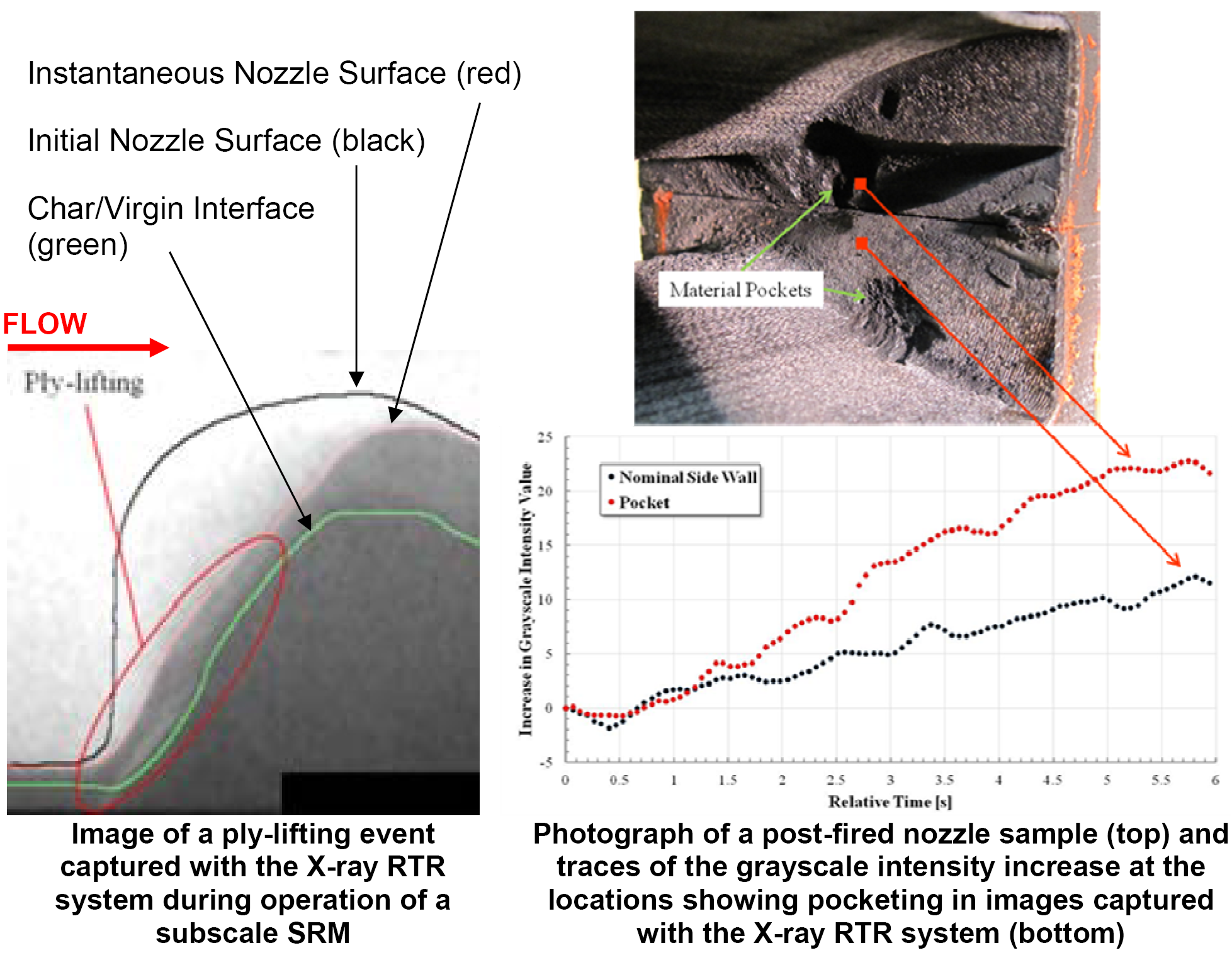
The following figures were acquired during the NASA-xUIP program studying CCP nozzle erosion. In addition to examining the nominal erosion behavior of nozzle samples, the X-ray RTR system is capable of detecting irregular erosion phenomena such as ply-lifting and pocketing.
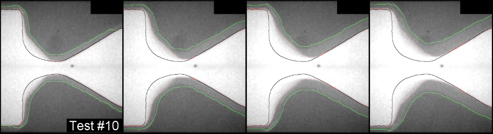
The following figure gives a sequence of X-ray Images captured during operation of a subscale SRM. Semi-automated enhancement of the raw Images through a recently developed methodology allowed identification of time-varying contours of the nozzle surface (red) and char/virgin location (green). Additional analysis of the Images allowed throat height and erosion rate variation with time to be deduced. Together with the pressure response of the subscale SRM, the deduced throat area allows for the approximation of the instantaneous mass flow rate, thrust, and Isp.